Cutaway Cross Section Reveal
The cutaway section: one quarter or one half removed to show what lives inside. This is the technical drawing that makes invisible structure visible.
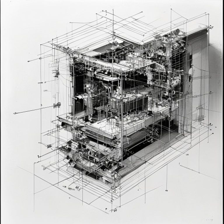
The prompt
Re-render this image as a technical cutaway cross-section drawing. The object or assembly is shown with a portion cleanly removed (typically one quarter front-left or one half front), the cut plane rendered as a straight line or slight angle exposing the internal mechanisms, chambers, layering, or structure beneath the exterior surface. Internal components are shown in black line work (0.5 to 0.8mm), with hidden edges indicated by dashed lines running behind opaque components. Cross-hatching or stippling fills the cut plane itself, using fine parallel lines or tight dot patterns (at 45-degree angle, standard mechanical drawing convention) to indicate the material of the cut surface. The exterior surfaces of the exposed object are rendered in clear black outline with minimal or no internal line work (those details are understood to be outside the cut plane). Dimension lines extend from critical internal measurements, with perpendicular terminator ticks. Reference numerals call out major internal features (no legible text). The background is white. The composition emphasizes the clarity of internal structure and the functional relationships between components. No shading or gradient, pure line work and pattern. Aspect ratio 4:3 or square depending on subject. Preserve the subject, pose, and composition of the source image exactly, change only the medium and rendering.
What it is doing
The cutaway is a fiction. You cannot actually remove a quarter of a working object and expect it to remain functional. But the cutaway drawing tells the truth about what you would find if you could. It reveals the hierarchy of function: the working parts, the structural frame, the power transmission, the hidden chambers. The cross-hatching on the cut plane serves two purposes: it marks the material that was removed, and it makes the depth of the object apparent through the pattern change. The cutaway is pedagogical honesty. It trades perfect representation for maximum understanding. This is the drawing style that dominates technical manuals for engines, pumps, boilers, any machinery with hidden internal geometry. The cutaway breaks the surface and exposes the secret logic underneath. This is also why it has been repurposed as the primary style for showing how buildings are constructed: the cutaway reveals the structural frame, the mechanical systems, the layering that makes the exterior possible. The cutaway is the drawing that says: here is what actually makes this work.
Tuning knobs
- Cut-plane-angle dial: `simple 90-degree vertical section cut` vs `45-degree diagonal cut exposing two internal zones` vs `complex multi-plane cutaway exposing multiple functional layers`
- Cross-hatch-density dial: `light parallel lines, 2mm spacing` vs `medium tight pattern, 1mm spacing` vs `dense stippled dot pattern, museum-archive weight`
- Internal-detail-density dial: `sparse interior, only major components` vs `moderate detail showing functional relationships` vs `complete mechanical layering, every chamber and passage`
- Cut-plane-materiality dial: `abstract hatch pattern indicating removed material` vs `color-coded hatch intensity by material type` vs `rendered with subtle grain or texture suggesting material composition`
- Exterior-simplification dial: `full exterior outline, minimal interior context` vs `moderate exterior detail with dominant interior focus` vs `exterior almost invisible, interior is the primary graphic`
- Reference-numeral-integration dial: `few callouts, major features only` vs `10-15 labeled components with leader lines` vs `comprehensive labeling, 20+ reference marks throughout`
Style lineage
Learn the visual culture this draws from: Core77.
Related prompts
See all 7 prompts in the Blueprint-Patent-Schematic grammar · Open in the gallery