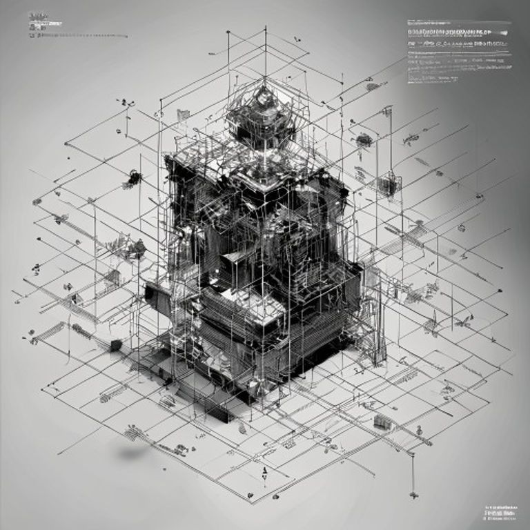
Exploded Axonometric Assembly Diagram
The exploded axonometric view: isometric geometry separated in space, each component floating where it belongs in the assembly sequence. This is how you tell someone how to put something together without using words.
The prompt
Re-render this image as an exploded axonometric (isometric or dimetric) assembly diagram. The isometric angle is precisely 30 degrees from horizontal. All components are shown separated in space along invisible vertical or diagonal construction lines, positioned in the exact order they stack during assembly. Primary components are rendered in black line work (0.5 to 0.8mm pen weight) with no shading or internal gradient. Smaller fasteners, screws, washers, pins are shown at multiple scales, typically 2x or 4x magnified in inset boxes to maintain clarity. Connection points are indicated with fine dashed lines or subtle arcs showing the trajectory of assembly. Components may be rendered with subtle shadow lines on lower and right edges to suggest three-dimensional form, but no cross-hatching and no fill. The background is white with occasional construction grid lines visible (light gray, 2mm intervals). Title area at top or side: render as a bare line-drawn cartouche with no legible text. The overall effect communicates assembly sequence through spatial separation and hierarchical scale without requiring written instruction. Aspect ratio 4:3 or 16:9. Preserve the subject, pose, and composition of the source image exactly, change only the medium and rendering.
What it is doing
The exploded view is a grammar of assembly. It separates the final product into components and shows them floating in the order they lock together. This is engineering without words. A person who has never seen the object before can look at the exploded diagram and understand how it goes together, where the fasteners live, which direction each piece travels, and what happens when you depart from the sequence. The isometric angle is standardized internationally so that distance, angle, and proportion remain true across all three dimensions simultaneously. The diagram is a promise: assemble in this order, at these proportions, and you will get a functioning object. The exploded view is the ancestor of every instruction manual, every IKEA diagram, every technical animation. It is the medium that solved the problem of teaching assembly to people who speak different languages. It is also the medium that makes assembly feel inevitable, predetermined, perfectable. There is no mystery left.
Tuning knobs
- Isometric-angle dial: `standard 30-degree isometric` vs `dimetric 45-degree angle` vs `cabinet projection with 45-degree recession`
- Component-scale dial: `all parts at comparable visual scale` vs `fasteners magnified 2-4x in inset boxes` vs `heavily magnified detail zones for small parts`
- Separation-spacing dial: `components tightly grouped, minimal separation` vs `moderate floating separation showing assembly flow` vs `maximum spread, components at exaggerated distance`
- Line-weight-variation dial: `uniform 0.5mm line weight throughout` vs `primary structure bold, fasteners fine` vs `progressive weight reduction toward detail`
- Shadow-and-depth dial: `pure line work, no shadow` vs `subtle shadow lines on lower-right edges` vs `half-tone shadow zones suggesting form`
- Assembly-sequence-indication dial: `components floating without directional cues` vs `subtle arcs or arrows showing assembly trajectory` vs `numbered sequence markers 1-N visible in or near each component`
Style lineage
Learn the visual culture this draws from: ArchDaily.
Related prompts
See all 7 prompts in the Blueprint-Patent-Schematic grammar · Open in the gallery